The Art of Electronics, 3rd Edition: Analog and Digital Guide
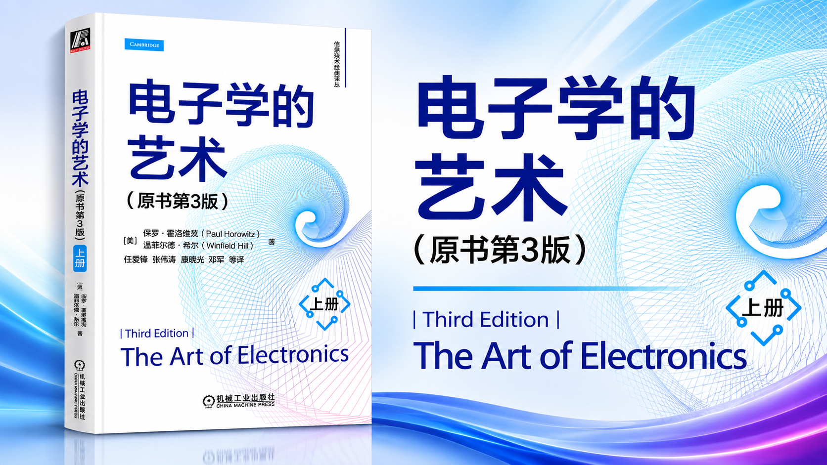
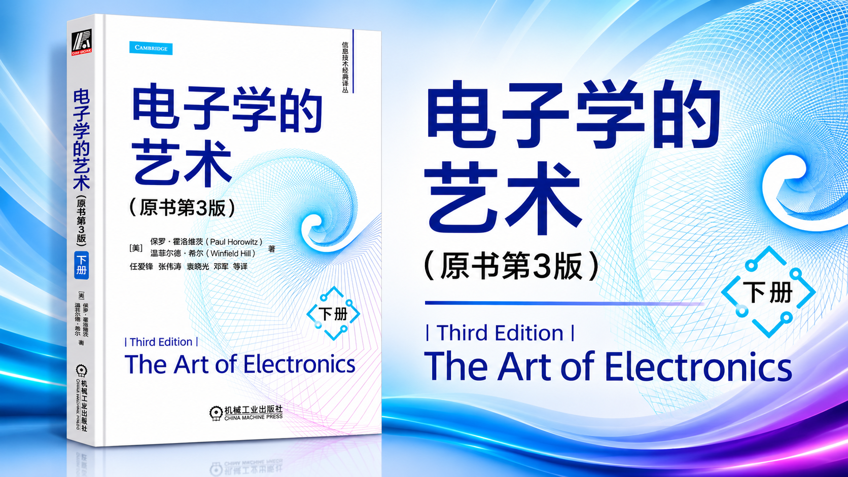
The Art of Electronics is a widely recognized textbook on practical electronic circuit design. Its third edition covers a broad range of subjects, starting with fundamental electrical components and analog circuits and progressing toward digital logic, data conversion, computer architecture, and microcontroller-based systems.
The material described here is organized into two volumes. Volume 1 focuses on analog electronics, developing the principles behind passive components, transistors, operational amplifiers, precision circuits, filters, oscillators, and low-noise design. Volume 2 focuses on digital electronics and system-level design, covering power conversion, logic circuits, programmable logic devices, digital interfaces, data converters, computer organization, and microcontrollers.
Together, the volumes provide a structured path from understanding individual electronic components to designing complete circuits and embedded systems.
📘 Volume 1: Analog Electronics #
Volume 1 contains eight chapters organized into four broad parts. It begins with basic electrical principles, moves into transistor and operational-amplifier design, and then applies those building blocks to practical analog circuits.
The material progresses from component-level behavior to complete signal-processing and measurement systems.
Part 1: Fundamentals of Electronics #
Chapter 1 — Basics of Electronics
The first chapter establishes the electrical principles needed for the rest of the book. It introduces the relationships between voltage, current, and resistance before examining how electronic signals behave in practical circuits.
Major topics include:
- Voltage, current, resistance, and basic circuit relationships.
- Signal characteristics and waveform behavior.
- Capacitance and alternating-current circuits.
- Inductors and transformers.
- Diodes and common diode circuits.
- Impedance, reactance, and frequency-dependent behavior.
- Passive electronic components and their practical characteristics.
- An AM radio as a comprehensive application example.
The chapter also addresses practical component identification, including confusing markings and very small electronic components.
The AM radio example is particularly useful because it brings several otherwise separate ideas together. Signals, passive components, filtering, impedance, and frequency-selective behavior all contribute to the operation of a real electronic system.
Part 2: Transistor Circuits #
Chapters 2 and 3 introduce the two major transistor families used throughout analog and electronic circuit design: bipolar junction transistors and field-effect transistors.
Chapter 2 — Bipolar Transistors
This chapter develops the operating principles of bipolar junction transistors (BJTs) and shows how they are used in practical circuit configurations.
Its coverage includes:
- Basic transistor operation and circuit configurations.
- The Ebers-Moll model and its application to basic transistor circuits.
- Transistor circuits used to construct amplifiers.
- Negative feedback and its effects on amplifier behavior.
- Typical transistor application circuits.
The discussion moves beyond simply treating a transistor as a current-controlled device. Understanding its operating region, bias conditions, and small-signal behavior is necessary when designing amplifiers that must operate predictably.
Negative feedback receives particular attention because it provides a foundation for controlling gain and improving the behavior of practical amplifier circuits.
Chapter 3 — Field-Effect Transistors
The third chapter turns to field-effect transistors (FETs), including junction FETs and MOSFETs.
Major subjects include:
- FET linear circuits.
- JFET characteristics and operating behavior.
- FETs used as electronic switches.
- Power MOSFET applications.
- MOSFET linear applications.
The chapter connects device characteristics with circuit-level decisions. JFETs and MOSFETs have different electrical characteristics from bipolar transistors, making them suitable for different applications.
Switching and power applications also introduce considerations such as gate drive, on-resistance, power dissipation, and device operating limits.
Part 3: Operational Amplifiers and Precision Circuits #
Operational amplifiers are among the most widely used building blocks in analog electronics. Chapters 4 and 5 develop the theory and practical design techniques required to use them effectively.
Chapter 4 — Operational Amplifiers
This chapter introduces operational amplifiers and progresses from basic circuit configurations to more advanced application and performance considerations.
Its coverage includes:
- Operational amplifier fundamentals.
- Basic inverting and non-inverting circuits.
- Practical operational amplifier applications.
- Detailed amplifier performance characteristics.
- More advanced operational amplifier circuits.
- Single-supply amplifier configurations.
- Different amplifier architectures and operational amplifier types.
- Typical application circuits.
- Frequency compensation in feedback amplifiers.
An ideal operational amplifier model is useful for understanding basic circuit relationships, but real devices have finite gain, limited bandwidth, input offsets, bias currents, and output constraints.
Understanding these limitations is necessary when selecting an amplifier and predicting how a circuit will behave under actual operating conditions.
Frequency compensation is another important subject. An amplifier that works correctly at low frequencies may become unstable when feedback, capacitive loading, and frequency-dependent gain interact. Compensation techniques help control this behavior.
Chapter 5 — Precision Circuits
Precision analog design requires more than choosing an operational amplifier with a high nominal gain. Small errors in resistors, references, input stages, and output stages can accumulate and affect the final measurement.
Chapter 5 examines the techniques used to design and evaluate precision circuits.
Key topics include:
- Precision operational amplifier design techniques.
- A practical millivoltmeter design example.
- Error budgets and unspecified device parameters.
- Zero-offset precision amplifier design.
- Component tolerances and their contribution to circuit errors.
- Operational amplifier input and output errors.
- Rail-to-rail input and output (RRIO) amplifiers.
- Selecting precision operational amplifiers.
- Auto-zero and chopper-stabilized amplifiers.
- A precision digital multimeter design example.
- Differential and instrumentation amplifiers.
- Fully differential amplifier circuits.
The chapter’s treatment of error budgets is especially relevant to measurement-system design.
A precision circuit must account for multiple error sources, including resistor tolerances, input offset voltage, input bias current, common-mode limitations, output swing, and temperature-dependent behavior.
The discussion of RRIO amplifiers also helps clarify an important selection issue: rail-to-rail specifications do not mean that every performance parameter remains ideal near the supply rails. Input common-mode range, output drive capability, distortion, and other characteristics still need to be checked against the device datasheet.
The chapter’s instrumentation-amplifier material connects these principles to sensor interfaces, bridge measurements, industrial instrumentation, and other applications where small differential signals must be measured accurately.
Part 4: Applied Analog Circuits #
The final three chapters apply the earlier concepts to frequency-selective circuits, signal generation, timing, and low-noise design.
Chapter 6 — Filters
This chapter introduces passive and active filters.
Topics include:
- Filter fundamentals.
- Passive filter circuits.
- Active filter circuits.
Filters are used to select or suppress particular frequency ranges in electronic systems. They appear in audio circuits, communication equipment, sensor interfaces, measurement systems, and signal-conditioning stages.
Passive filters use components such as resistors, capacitors, and inductors. Active filters commonly use operational amplifiers alongside resistors and capacitors, allowing designers to implement frequency-selective circuits with gain and without necessarily requiring inductors.
Understanding filter behavior involves more than calculating a cutoff frequency. Designers must also consider passband gain, attenuation, phase response, component tolerances, and the interaction between filter stages.
Chapter 7 — Oscillators and Timers
The seventh chapter examines circuits that generate periodic signals and provide timing functions.
Its two main subjects are:
- Oscillator circuits.
- Timer circuits.
Oscillators generate repeating waveforms and are used in clock generation, signal sources, communication circuits, and control systems.
Timer circuits provide controlled delays, pulse generation, and timing sequences. Depending on their architecture, they may use analog feedback, timing capacitors, threshold detection, or dedicated integrated circuits.
These applications bring together several concepts introduced earlier, including amplifier behavior, capacitors, feedback, switching, and frequency response.
Chapter 8 — Low-Noise Techniques
Noise limits the smallest signal that an analog circuit can detect or process accurately. It is particularly important in precision measurement, sensor interfaces, communication receivers, and low-level signal amplification.
Chapter 8 examines noise mechanisms and practical methods for reducing their influence.
Major topics include:
- Noise fundamentals.
- Signal-to-noise ratio and noise figure.
- Noise in bipolar transistor amplifiers.
- Calculating equivalent input noise from noise figure.
- Low-noise design using bipolar transistors.
- Low-noise design using JFETs.
- Comparing bipolar and FET noise characteristics.
- Noise in differential and feedback amplifiers.
- Noise in operational amplifier circuits.
- Signal transformers and their noise behavior.
- Noise in transimpedance amplifiers.
- Noise measurements and noise sources.
- Bandwidth limiting and RMS voltage measurement.
- Improving signal-to-noise ratio through bandwidth reduction.
- Power-supply noise.
- Interference, shielding, and grounding.
The chapter connects device-level noise characteristics with complete circuit performance.
For example, selecting a low-noise transistor does not automatically produce a low-noise amplifier. Source impedance, bandwidth, resistor values, gain distribution, power-supply quality, and PCB layout can all affect the noise measured at the output.
The sections on shielding and grounding are also important because electromagnetic interference and unwanted current paths can introduce noise that cannot be solved simply by replacing an amplifier or transistor.
For additional reading on practical analog design, see Design with Operational Amplifiers and Analog ICs: A Practical Guide, which explores operational amplifier behavior, feedback, filtering, noise, stability, and analog integrated-circuit applications.
💻 Volume 2: Digital Electronics #
Volume 2 contains seven chapters covering the power, logic, conversion, and computing technologies used in modern electronic systems.
Its structure begins with voltage regulation and power conversion, moves through digital logic and programmable devices, and then connects analog and digital systems through data converters. The final chapters introduce computer architecture, communication interfaces, and microcontrollers.
Part 1: Voltage Regulation and Power Conversion #
Chapter 9 — Voltage Regulation and Power Conversion
Every electronic system requires a suitable power supply. Different circuit blocks may need different voltage levels, current capabilities, and noise characteristics.
Chapter 9 examines the circuits and techniques used to generate and regulate those supplies.
Major topics include:
- Zener diodes and series-pass linear regulators.
- Basic linear regulators using the classic μA723.
- Integrated linear voltage regulators.
- Thermal management and power design.
- AC mains input and unregulated power supplies.
- Switching regulators and DC-DC converters.
- AC-powered off-line switching converters.
- Practical power-converter design examples.
- Inverters and switching amplifiers.
- Voltage references.
- Commercial power modules.
- Energy storage using batteries and capacitors.
- Additional power-regulation techniques.
The chapter covers both linear and switching regulation.
Linear regulators are relatively straightforward and can provide low-noise outputs, but they dissipate power according to the voltage difference between their input and output. This makes thermal design an essential part of the circuit.
Switching regulators use high-frequency switching and energy-storage components to convert voltage levels more efficiently. Their design introduces additional considerations, including switching frequency, inductor selection, control-loop stability, ripple, electromagnetic interference, and layout.
The sections on off-line converters and inverters extend the discussion from low-voltage DC regulation to larger power-conversion systems.
Part 2: Digital Logic and Programmable Devices #
Chapters 10 and 11 introduce digital circuit behavior, common logic families, and programmable logic hardware.
Chapter 10 — Digital Logic
This chapter establishes the fundamentals of digital logic and the design of combinational and sequential circuits.
Topics include:
- Basic digital logic concepts.
- CMOS and bipolar TTL integrated circuits.
- Combinational logic design.
- Sequential logic design.
- Sequential functions implemented with integrated circuits.
- Typical digital circuit applications.
- Low-power digital circuit design.
- Digital logic troubleshooting.
Combinational circuits produce outputs based on their current input values. Sequential circuits also depend on stored state, making clocks, flip-flops, registers, and timing relationships important.
The chapter connects these concepts to real integrated circuits and practical troubleshooting. Understanding how logic families operate electrically is just as important as understanding Boolean expressions, particularly when different devices must communicate with one another.
Low-power design is another practical concern. Switching activity, supply voltage, load capacitance, and circuit architecture all influence the power consumed by digital logic.
Chapter 11 — Programmable Logic Devices
Programmable logic devices (PLDs) allow designers to implement digital logic functions using configurable hardware rather than constructing every function from fixed logic components.
This chapter covers:
- A brief history of programmable logic devices.
- The hardware architecture of PLDs.
- A pseudorandom byte-stream generator design example.
- Practical design suggestions.
The architecture discussion introduces how programmable hardware represents and implements logic functions.
The pseudorandom byte-stream generator provides an application example that connects logic design with state machines and digital sequence generation.
PLDs are useful in applications that require custom logic, interface adaptation, timing control, or hardware functions that would otherwise require numerous discrete logic components.
Part 3: Logic Interfaces and Digital-to-Analog Conversion #
Chapters 12 and 13 address the boundaries between digital devices and the electrical world around them.
Chapter 12 — Logic Interfaces
Digital components cannot always connect directly to one another or to external equipment. Differences in voltage levels, current requirements, timing, and electrical loading must be considered.
This chapter examines the techniques used to connect digital circuits reliably.
Major topics include:
- CMOS and TTL logic interfaces.
- Probing and measuring digital signals.
- Comparators.
- Driving external loads from logic-level outputs.
- Optoelectronic emitters and detectors.
- Optocouplers and relays.
- Fiber-optic digital communication.
- Digital signals transmitted over long wires.
- Cable-driving techniques.
Logic-level compatibility is a basic but frequent source of hardware problems. A signal that represents a logical high for one device may not satisfy the input requirements of another device.
The chapter also examines how to connect digital logic to external loads. LEDs, relays, cables, and other devices may require more current or voltage than a logic output can provide directly.
Optocouplers and fiber-optic links introduce electrical isolation or optical transmission, which can be useful when systems need to reduce ground-loop problems, handle electrical interference, or communicate across different electrical environments.
Chapter 13 — Digital and Analog
Digital systems operate on discrete logic values, while the physical world produces continuously varying electrical signals. Analog-to-digital converters (ADCs) and digital-to-analog converters (DACs) provide the interfaces between these two domains.
Chapter 13 develops the fundamentals of data conversion and examines common converter architectures.
Its coverage includes:
- Basic digital and analog conversion concepts.
- Digital-to-analog converter architectures.
- DAC application examples.
- Converter linearity and accuracy.
- Analog-to-digital converter fundamentals.
- Flash ADCs and parallel encoders.
- Successive-approximation ADCs.
- Integrating ADCs.
- Delta-sigma ADCs.
- ADC selection and performance trade-offs.
- Other ADC and DAC architectures.
- Complete A/D conversion systems.
- Phase-locked loops.
- Pseudorandom bit sequences and noise generation.
Different converter architectures are suited to different applications.
Flash converters can provide very high conversion speeds but generally require more hardware as resolution increases. Successive-approximation converters offer a widely used balance between speed, resolution, and implementation complexity. Integrating and delta-sigma architectures are often selected for applications where resolution and noise performance are more important than very high conversion speed.
Converter selection also requires attention to more than nominal resolution. Important specifications include:
- Sampling rate.
- Quantization resolution.
- Integral and differential nonlinearity.
- Offset and gain errors.
- Signal-to-noise ratio.
- Effective number of bits.
- Reference-voltage quality.
- Input bandwidth and settling behavior.
The chapter’s treatment of complete conversion systems helps connect converter specifications with the analog signal path, reference source, digital interface, and application requirements.
Phase-locked loops extend the discussion into frequency synthesis, synchronization, and control of signal timing. Pseudorandom sequences and noise generation provide additional examples of digital techniques used in signal-processing applications.
Part 4: Computers, Controllers, and Embedded Systems #
The final two chapters move from individual digital circuits to programmable computing systems.
Chapter 14 — Computers, Controllers, and Data Links
This chapter introduces the architecture of computer systems and the interfaces used to move data between processors, memory, and peripheral devices.
Major subjects include:
- CPU architecture and data buses.
- Computer instruction sets.
- Bus signals and interfaces.
- Memory technologies.
- Other bus architectures and data links.
- Parallel buses and communication links.
- Serial buses and communication links.
- Data formats.
The CPU and bus architecture sections explain how a processor communicates with other parts of a system. Instruction-set concepts describe the operations a processor can execute, while memory and interface discussions show how instructions and data move through the hardware.
Parallel and serial communication are both covered. Parallel interfaces transfer multiple bits across multiple signal lines, while serial interfaces transmit data over fewer physical connections.
The choice between these approaches depends on factors such as data rate, physical distance, connector complexity, signal integrity, and system architecture.
Understanding these interfaces is essential when integrating processors, memory devices, sensors, converters, and external controllers.
Chapter 15 — Microcontrollers
The final chapter introduces microcontrollers and their use in complete embedded applications.
Unlike a general-purpose computer that may depend on separate processor, memory, and peripheral components, a microcontroller typically integrates a processor core with memory and peripheral interfaces into a compact device.
The chapter covers:
- Microcontroller fundamentals.
- A sunshine-monitor design example.
- An overview of common microcontroller architectures.
- An AC power-control design example.
- A frequency-synthesizer design example.
- A temperature-controller design example.
- A stabilized mechanical-platform design example.
- Microcontroller peripheral integrated circuits.
- Development environments and tools.
- Additional microcontroller topics.
The application examples demonstrate how microcontrollers connect software with real electronic hardware.
A sunshine monitor, for example, can combine a sensor interface, analog signal conditioning, data conversion, and firmware processing. A temperature controller can use sensor measurements to determine when a heater or cooling device should be activated.
The AC power-control and frequency-synthesizer examples introduce more specialized timing and control requirements. The stabilized mechanical-platform example extends the discussion toward systems involving sensors, actuators, and feedback control.
Microcontroller peripherals are also important because many embedded designs depend on timers, communication interfaces, analog inputs, PWM outputs, and interrupt handling.
Development environments provide the tools required to write, compile, program, and debug the firmware running on these devices.
For a practical example of controller hardware and firmware organization, see IT8528E Embedded Controller Firmware Architecture and Code Flow. It provides a complementary look at controller peripherals, firmware structure, timers, PWM, and related embedded functions.
🔗 How the Two Volumes Fit Together #
The two volumes cover different areas of electronics, but they are closely connected in practical engineering work.
Volume 1 develops the analog building blocks used to sense, amplify, filter, and condition electrical signals. Volume 2 shows how those signals can be converted into digital data, processed by logic or programmable controllers, and integrated into complete electronic systems.
A typical embedded measurement system illustrates how the topics fit together:
- Power supply: A regulated power-conversion circuit provides suitable supply voltages for the system.
- Sensor interface: A sensor produces an electrical signal in response to a physical quantity.
- Analog conditioning: Transistors and operational amplifiers amplify or condition the signal.
- Filtering: Analog filters reduce unwanted frequency components and interference.
- Data conversion: An ADC converts the analog signal into digital data.
- Digital processing: A microcontroller processes the measurements and executes the application logic.
- Output control: Digital interfaces, timers, and PWM signals control external devices.
- System communication: Serial or parallel data links connect the system to other equipment.
This example demonstrates why analog and digital electronics should not be treated as completely separate disciplines. Even a predominantly digital embedded product depends on analog interfaces, stable power, signal integrity, and correct electrical integration.
🎯 Who Should Study The Art of Electronics? #
The two volumes are relevant to readers at different stages of electronics education and engineering practice.
Students and beginners can use the material to build a foundation in electrical principles, electronic components, transistor circuits, and digital logic. The progression from individual components to complete systems helps connect theoretical concepts with practical circuit behavior.
Electronics engineers can use the material as a reference when working with analog signal processing, precision measurement, power supplies, logic interfaces, and mixed-signal systems.
Embedded systems developers will find the second volume particularly relevant because it connects digital logic, data conversion, computer architecture, and microcontroller applications.
Hardware designers can use the combined coverage to understand how circuit-level decisions influence system performance, including noise, power consumption, timing, and interface compatibility.
The books are also useful for engineers who work primarily in software but need a better understanding of the hardware beneath their embedded applications.
🛠️ A Practical Learning Path #
The chapter organization supports a progressive study approach.
For readers who are new to electronics, beginning with the first chapter of Volume 1 is the natural starting point. Understanding voltage, current, impedance, capacitance, inductance, and signals makes the later transistor and amplifier chapters much easier to follow.
Readers who already understand basic circuit theory can place more emphasis on the transistor, operational-amplifier, precision-circuit, and low-noise chapters.
For digital and embedded work, the second volume can be approached in a similar sequence:
- Study voltage regulation before debugging or designing digital hardware that depends on stable power.
- Learn digital logic before moving into programmable logic devices.
- Study logic interfaces before connecting external devices and communication links.
- Understand ADC and DAC principles before designing mixed-signal systems.
- Review computer architecture and data links before working with microcontrollers.
- Use the microcontroller design examples to connect hardware knowledge with firmware development.
Practical exercises are particularly valuable. Building a simple amplifier, measuring a filter’s frequency response, testing a voltage regulator, or programming a microcontroller can reveal details that are difficult to appreciate from equations alone.
When working with physical circuits, always check component ratings, supply limits, power dissipation, grounding, and measurement-equipment requirements. Mains-powered converter circuits require appropriate isolation and electrical safety procedures.
📚 Scope of the Third Edition #
Across both volumes, The Art of Electronics, 3rd Edition, covers a wide range of electronics topics:
| Area | Main subjects |
|---|---|
| Basic electronics | Voltage, current, resistance, signals, passive components |
| Semiconductor devices | Diodes, BJTs, JFETs, MOSFETs |
| Analog circuit design | Amplifiers, feedback, filters, oscillators, timers |
| Precision electronics | Error budgets, instrumentation amplifiers, precision measurement |
| Low-noise engineering | Noise sources, noise figure, shielding, grounding |
| Power electronics | Linear regulators, switching converters, inverters, references |
| Digital systems | CMOS, TTL, combinational and sequential logic |
| Programmable hardware | Programmable logic devices and digital generators |
| Digital interfaces | Comparators, optocouplers, fiber links, cable drivers |
| Mixed-signal design | ADCs, DACs, PLLs, conversion systems |
| Computer architecture | CPUs, instruction sets, memory, buses, data formats |
| Embedded systems | Microcontrollers, peripherals, firmware development |
The main strength of this two-volume arrangement is its breadth. It connects fundamental electrical behavior with practical analog circuits, digital hardware, power systems, data conversion, and embedded computing.
For readers who want to understand how electronic systems work from the component level up to complete hardware applications, the material provides a broad engineering foundation across both analog and digital design.